
The magnetic north (or azimuth) recorded by most magnetic survey instruments is liable to error, due to magnetic disturbances caused by casings of nearby wells.
To overcome these errors, gyroscopes are used because of their ,ability to maintain a preset direction, irrespective of the earth’s magnetic field or factors disturbing it. Gyros are most widely used in orienting mud motors and bent sub assemblies in areas where magnetic instruments will be influenced by magnetic fields of nearby casings, as in platform drilling.
The principal element of the gyro is a rapidly spinning weighted wheel , which maintains a preset direction by resisting changes in direction, owing to its inertia. Thus, if the wheel is made to rotate parallel to the earth’s axis of rotation (i.e. N-S direction), then it will maintain this direction, thereby serving as a direction indicator.
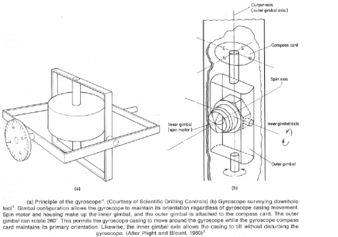
The axis of the wheel is horizontal and is mounted inside two perpendicular gimbals to allow the gyro to maintain its direction irrespective of gyro casing movement. The inner gimbal is made up of the spin motor and the housing. The motor spins at a rate between 18000 and 42 000 rpm, depending on gyro size and type of spin motor used.
The outer gimbal is fitted with a compass card similar to that used in the magnetic single shot. The compass card is set to a known direction, normally to the north, to serve as a reference for survey directional data. The pendulum assembly, a single-shot camera (for
gyro single shot) and a timer are fitted above the compass card. The orientation of the gyro compass must be checked prior to running in hole, which is done by aligning the tool to a known reference direction by use of a telescope alignment kit. For single shot the gyro assembly is then run on wire line to hole bottom. A picture of the angle-indicating unit
(i.e. plumb bob and gyro compass) is taken at the required depth. The survey tool is pulled out of hole to surface and the gyro film is retrieved. The film is developed and placed in a chart reader to determine hole direction and hole inclination.
For gyro multi-shot, the procedure is to lower the tool on wire line through a section of cased well bore. The tool is stopped at set depth intervals, e.g. every 100 ft, and a survey is taken by the multi-shot camera. Some check surveys are taken on the outrun, typically every 400 ft. All gyros have a tendency to drift from their preset direction, and survey readings should be corrected for this effect. Drift is due entirely to friction in the bearings of the spinning wheel, gyro imbalance and motor speed instabilities. During surveying, the tool is kept stationary every 15 min for 5 min, to monitor gyro drift.
References: Oil well drilling engineering Principles and Practices – H. Rabia
